If you have visited my blog before, you most likely know that I have built several modules for the Microsoft Gadgeteer platform. So far I have only tried simple modules (with the exception of POE module). What I haven’t tried yet is a DaisyLink module. DaisyLink module is a special (smart) breed of modules because it has to have a dedicated controller in order to communicate with the main board. Recently I had a chance to finally built a module like that and I would like to share my experience in that area. There is a lot to write about, so I will do it in multiple posts. This is the first post where we look at the DaisyLink protocol.
Why does a DaisyLink module need its own MCU on board? A DaisyLink module can be a part of a long chain of modules connected to each other.
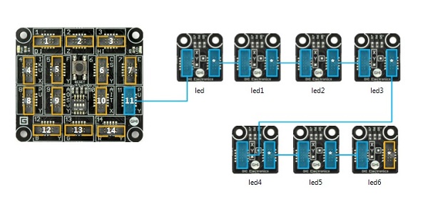
One chain can have more modules than the number of pins that are available on the socket that the chain is connected to. So we would need a smart way of communication that requires a minimal number of physical connections. The main board needs a way to distinguish and address each individual module in the chain as well. In other words, the main board should be able to assign an address to a module and the module should remember that address in some sort of memory. The communication between the main board and a module should also be generic enough and independent from the actual functionality that is provided by that module. In order to meet these requirements the Gadgeteer team designed a special protocol - the DaisyLink protocol. This protocol has to be implemented on a module’s micro controller.
Memory Map
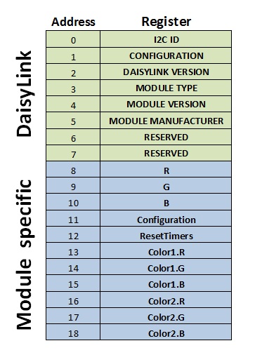
Before we start looking at the protocol details lets take a look at the module’s memory organization. As mentioned before, each module is given an address by the main board and that address is stored, along with some other settings, in the module’s Memory Map. The total size of the Memory Map is 256 bytes. The first 8 bytes are allocated for the DaisyLink infrastructure.
Remaining 248 are available for the module. This module-specific area of the map is the mechanism of controlling the module. As the module designer, you will lay out this map by defining your own registers that required to tell your module what to do as well as registers to store results of these actions if needed. For example this is the map layout for the GHI’s Smart Multicolor LED Module.
For example, byte at address 11 controls mode of the module (On, Off, Blinking, etc.)
Wiring
The DaisyLink Protocol is based on I2C. I2C is a common protocol supported on all major MCUs available today. It requires two wires - one for clock (SCL) and one for data (SDA).
If you have never worked with I2C, I strongly recommend to read about it on the Internet. There are plenty of tutorials available (I have included one link at the end of this post).
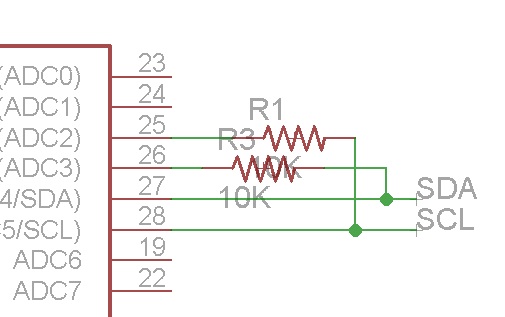
I2C bus requires two pull-up resistors for both lines. At first, it would make sense to put these resistors on the main board, but that would limit the use of the socket. So the decision was to have a pair of pull-up resistors (10k) on each module. Each module should be able to switch these resistors on and off. This will ensure to have only one pair of active resistor on the bus. The protocol specification shows how to use a transistor to implement a switchable pull-up. We will be using the other way of doing it by utilizing tri-state ports on the micro controller. For example, in the schematic below, changing the pin 25 to digital out and setting it to HIGH will enable the SCL pull-up resistor; switching the pin to digital input will disable the pull-up. Same applies for the pin 26 for the SDA line.
In addition to I2C wires, DaisyLink requires two more connections, one to the module or main board up the stream and one to the module down the stream. Here is the schematic view of both connectors:
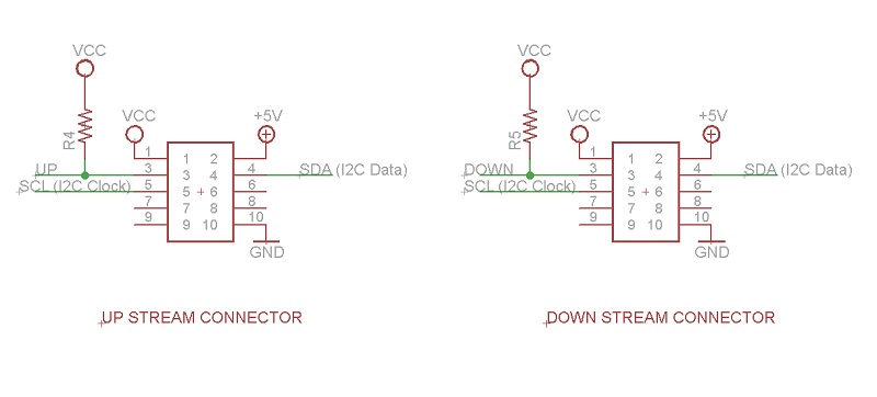
Upstream and downstream lines are pulled high on each module using 10K pull-up resistors. Pulling these lines down will allow a module and/or the main board to signal each other about the state changes. Notice the extra unused pins on each socket (pins 6,7,8 and 9). We will use them later during actual implementation of the module.
Module states
At any given time a DaisyLink module can be in one of the four states. Below is the table from the official specification document that describes the four states as well as the state of the bus for each module state.
| State | Upstream | Downstream | I2C pull-ups |
|---|---|---|---|
| Reset | Driven low by main board | Driven low by module | Disabled |
| Setup | Released by main board and pulled high by module’s pull-ups | Driven low by module | Active |
| Standby | Pulled high by module’s pull-ups | Released by module and pulled high by module’s pull-ups | Active |
| Active | Pulled high by module’s pull-ups | Pulled high by module’s pull-ups | As set by the main board |
Lets look at each state in more details.
Reset
On a power up each module is in the Reset state - the upstream line is driven low by the upstream neighbor. If it’s the first module in the chain, the upstream neighbor is the main board. Downstream is driven low by the module (to ensure that all the other modules in the chain stay in the Reset state). At this state a module should listen for the level change on the upstream line. As soon as it goes HIGH it should proceed to the next state. (If upstream line goes low again at any state, this takes the module back to the Reset state).
Setup
First thing to do after switching into the setup state is to activate pull-up resistors and enable I2C interface on the micro controller. Remember that every module is I2C slave, so if your micro controller has different initialization for master and slave, make sure you are using it as a slave device. The default I2C slave address during setup is 127. During the Setup stage the main board reads module’s register at address 2. This is the DaisyLink protocol version (current number is 4). If the module returns correct version number then the main board assigns a new unique ID for the module by writing it to the the modules register at address 0. As soon as the new ID is assigned, the module goes into the Standby state and should release the downstream line. This will let the next module in the chain to move from Reset to Setup state.
Standby
Nothing to do here. During this state the main board tries to read protocol version of the next module that will respond to the default address of 127.
Here is the image of the state of the neighbor lines (0 - upstream, 1- downstream).
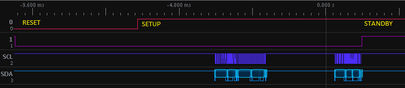
(The image above is taken from SUMP Logic analyzer software. For hardware I used BusPirate )
Reading and writing of the memory map is done by implementing standard I2C-based EEPROM interface
A write transaction comprises the following bytes:
- A start condition.
- The I2C ID with the write bit set (ID 1–127, LSB 0=write).
- The memory address to write (0–255).
- One or more bytes of data to write.
- A stop condition.
A read transaction includes the following bytes:
- A start condition.
- The I2C ID with the write bit set (ID 1–127, LSB 0=write).
- The memory address to read (0–255).
- A repeated start condition (or stop condition and then start condition).
- The I2C ID with the read bit set (ID 1–127, LSB 1=read).
- One or more bytes of data that are written by the subordinate device clocked in by the master according to the I2C specification.
- A stop condition.
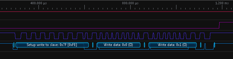
I2C transactions to read version number:
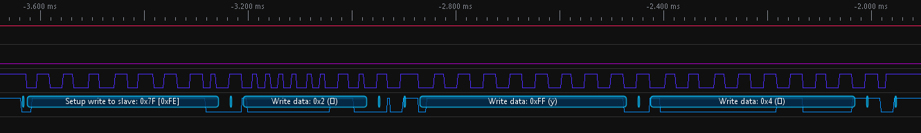
I2C transactions to assign new ID to the module:
Active
After the main board is done assigning unique IDs to each module in the chain, it will notify all the modules, except the last one, to turn off the pull-up resistors. This is done by writing to the configuration register at address 1 in the memory map. Bit 0: low=pull-ups are off, high=pull-ups are on. The main board will also write to the Bit 1: low=module in Active state, high=module is not initialized.
I hope I have provided enough details about how the DaisyLink protocol works. If you have any questions/suggestions feel free to leave a comment. In the next post I will show my implementation of the protocol on Arduino.
Gadgeteer DaisyLink Series:
- Gadgeteer DaisyLink - Protocol (this post)
- Gadgeteer DaisyLink - Arduino Library
- Gadgeteer DaisyLink - Arduino Sketch
Links: